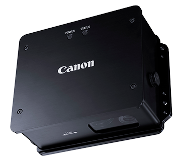
PD-704
PD-704
Measure the velocity and length without contacting moving target to prevent staining and damaging with high-speed up to 100 G of acceleration and features a depth detection range of ±15 mm.
Key Features
Developers’ Story
A Unique Measuring Technology to Solve Problems at Production Sites
Hear from the engineer behind this innovative device as he shares the challenges and triumphs of developing a unique algorithm capable of processing up to 4,000 images per second.
Interview with Clients
Discover the Impact of Canon’s Non-Contact Displacement Sensor!
Find out how it has nearly tripled the lifespan of our customer Daikure’s steel processing machine blades, while significantly reducing time and labour costs.
Features
Non-Contact Measurement
Perform precious measurement of moving target without staining/damaging objects.
Tracking High Acceleration
Tracking fast acceleration (up to 100 G) by Canon Original Profile machining technology.
Safe Operation with White LED
No need for safety precautions to protect against laser radiation.
Application Examples
Non-Contact Displacement Sensor |
Frequently Asked Question
What kind of objects are suitable for measurement?
It covers a wide range of products, including steel, paper, wire rods, housing materials, textiles, food products (chocolate, cheese, etc.), concrete, asphalt, and pedestrian crossings.
However, the measurement accuracy varies depending on the surface condition of the object. We recommend that you conduct a demonstration in advance.
What kind of things can't be measured?
These include glossy paper, slippery surfaces, fine threads, and cables, transmitting films, glass, and surfaces where the edges of the fluorescent light are clearly visible on the measuring surface.
Is it possible to measure curved surfaces?
It's possible. However, if the object is too thin, you may not be able to see the surface well.
If the object to be measured is cylindrical, is there a limit to the size of the object?
Stable measurement is possible for diameters of about 40 mm or more. However, the measurement accuracy varies depending on the surface condition of the object. In some cases, diameters of Φ40 mm or less can be measured, but this will affect the measurement accuracy.
Is there an effect of ambient light?
It has no impact in general use.
Can I use this product in an environment where water, oil, and dust are scattered?
Yes, you can. The standard is IP65 compliant. Please attach a special cable and a special cap that is dustproof and waterproof.
Is it possible to measure workpieces with processing oil on them?
It can be measured without any problems. In addition, if there is a possibility of oil adhering to the PD series, we recommend using the optional protective cover unit.
Is it possible to measure in an environment where vibrations are propagated to the device?
There is no problem with some vibration. However, the less vibration there is, the better the accuracy of the measurement.
It is recommended to devise the mounting position and jig of the PD series to measure.
What should I do when the amount of reflected light of the object to be measured is large and I cannot measure it well?
There is a possibility that it can be measured well by changing the measurement mode. For details, please refer to "Mode Function".
If warning still occurs, it may be possible to measure by reducing the amount of reflected light using the ND filter provided by the customer.
How to operate with a cutting device (or processing equipment)?
Connect the I/O cable from the PD series to the external Programmable Logic Controller (PLC) or sequencer to count the pulse signals from PD series.
How is the cutting precision set to control the cutting position?
Counting the pulses detected by the external PLC or sequencer, and then send a trigger signal to the cutting equipment.
What kind of signal do you have?
Line driver output. In addition, there are GND, error signal, warning signal, reset signal, and trigger input signal.
How to import it into the data logger?
Counting the pulse signal. Please note that the PD series does not provide an analog output.
What kind of PLCs can be used?
Please select a device that can capture line driver signals. The PD series outputs a pulse signal according to the amount of movement.
As the speed increases, the pulse frequency becomes high, so a high-speed counter is required.
What is the recommended counter unit?
Mitsubishi Electric’s CC-Link high-speed counter unit AJ65BT-D62D does support line driver input.
If the pulse width setting is at the default of 10 um, it will be 4 m/s → 400 kHz, which matches the maximum speed of this counter. But, if the pulse width setting is reduced, it will exceed the maximum range, so caution is advised.
The AJ65BT-D62 does not support line driver input, so it cannot be used for PD series.
How to import speed information into the processing equipment?
Use a PLC to capture the pulse signal of the PD series and convert it to speed.
Is a difference in connection between the PD series and the laser Doppler speedometer?
The PD series has only a line driver output, but the laser doppler speedometer has a BNC pulse output, a BNC analog output, a line driver output from the D-SUB connector, and an open collector output.
What are the different types of triggers?
There are step shapes and pulse shapes. The voltage is 5~24 V, and the pulse width is more than 0.1 s.
Can I use the included application software with my processing equipment?
No. Please understand that it is a basic software intended for evaluation purposes.
Is it possible to measure the PLC connection and the PC application at the same time?
It is possible to support from application software V1.2 and main unit firmware V1.1 onwards. Please check [Help] → [Version] in the menu bar of the app software.
How to measure the length of a cut steel plate?
There are two measurement methods.
- Method of using an external trigger using a photoelectric sensor, etc.
In this case, separate triggers are required to start and end measurement. We recommend a photoelectric sensor for the trigger, but the conveyance speed and the response speed of the photoelectric sensor will affect the measurement accuracy, so please pay attention to the response of the photoelectric sensor and the mounting position. Also, depending on the target object and measurement environment, there is a possibility that it may not be possible to measure even if a photoelectric sensor is used.
- How to use full length measurement mode
In this case, it is possible to measure the entire length of the object using only the PD series. For details on the measurement method, please refer to pages 41 to 43 of the software user's manual. This function is available from application software V1.2 and main unit firmware V1.1. Please check [Help] → [Version] on the menu bar of the application software.
When should the calibration be performed?
We recommend once a year.
What is the cost of calibration?
Please contact your dealer.
Are there any servicing items?
There are no replacement parts other than the LEDs. It is recommended to install a replaceable protective cover unit to prevent dirt and scratches from getting on the lens surface. If the lens surface gets dirty, clean it with a soft cloth to prevent scratches.
What is the lifespan of LEDs?
Depending on the usage environment, it will be about 10 years.
What is the actual range you are measuring?
The actual measurement area is 4.8 x 0.2 mm within the Φ30 mm illumination light. If alignment is difficult, use a measuring distance adjustment tool (optional).
Can you control the production line with this product alone?
No. The PD series is a measuring device that calculates the distance and speed of an object. Measured values can be output by A/B phase pulses, so please connect them to your PLC and use them in the production line system.
What is the continuous measurement time with the accessory software?
When measured at 40 Hz, it can be measured continuously for 600 seconds. If it is measured at 4 KHz, it can be measured continuously for 200 seconds.
How far away can you measure from the object?
Install within a range of 70 mm ± 15 mm from the object.The closer it is to 70 mm, the more accurate the measurement can be. It is recommended to use a measuring distance adjustment tool (optional) to accurately adjust the alignment.
What is the specific measurement accuracy?
Accuracy depends on the surface condition of the object and the measurement environment.
Is it possible to measure the length while the measurement object is moving?
If you press the measurement ‘start’ and ‘end’ buttons while the measurement target is moving, you will not be able to measure correctly. It is recommended that you start the measurement with the object stationery.
Specifications
Specifications
|
Measurement Method |
Profile Matching Method |
|
Light Source |
LED |
|
Measurement Distance |
70mm±15mm |
|
Measurement Speed Range |
-4,000mm/s to 4,000mm/s |
|
Maximum Acceleration of Target Measurement Object |
100G |
|
Measurement Resolution |
1µm |
|
Measurement Accuracy*1 |
|
|
WD: 70mm±5mm |
±0.2% |
|
WD: 70mm±15mm |
±0.5% |
|
Measurement Repeatability*2 |
0.02% |
|
Light Source |
LED |
|
Sampling Rate |
4kHz |
|
Pulse Output |
1µm to 1,000µm (Set on application software) Phase A/B (RS422-compliant line driver) |
|
Other Input/Output |
|
|
Trigger Input |
Photo coupler insulation: 5 to 24V |
|
Error Output |
Open collector output (Photo coupler insulation): 5 to 24V |
|
USB Interface |
USB 2.0 Full Speed (Compatible with USB 1.1) compliant |
|
Operating Temperature |
0°C to 50°C |
|
Storage Temperature |
-30°C to 50°C |
|
Humidity |
90% RH or lower |
|
Vibration |
Bare vibration evaluated in vibrating environment |
|
Protection Class*3 |
IP65 |
|
Power Voltage |
DC12V to 24V |
|
Power Consumption |
8W |
|
Weight |
1.2kg |
|
Dimensions |
180 x 135 x 67mm |
|
Materials |
Aluminum, Window (Stain proof coating) |
|
Cable Length |
|
|
Power Cable |
5m |
|
I/O Cable |
5m |
|
USB Cable |
5m |
- When measured in our environment.
- When measured in our conditions.
- When used the optional kit.
Product Disclaimer
- 01. Please refer to individual country / region websites and respective sales offices for product availability.
- 02. Specifications, availability and terms of offers may change without notice.
- 03. Products / Services may be manufactured by and/or supplied to us by third party manufacturers / suppliers for distribution / resale (non-Canon brand products).

